How to Reduce Energy Loss in Solar Conversion Systems?

Time:2026-09-16 Author:Henry
0%

How to Reduce Energy Loss in Solar Conversion Systems?

Solar conversion systems rarely lose energy at one single point. Losses accumulate quietly, like heat along a crowded electrical pathway. Photovoltaic cells reflect part of the sunlight before absorption. They also lose energy through thermalization, recombination, and imperfect charge collection. Resistance in metal contacts and cables creates additional heat. Inverters introduce conversion losses, while shading, dust, cell mismatch, and aging reduce practical output.

David Faiman, a respected solar-energy researcher, once said, “The sun is a very large nuclear reactor in the sky.” His observation highlights the enormous resource available, but it also exposes a practical challenge. Capturing sunlight is not enough. Engineers must preserve its energy through every conversion stage.

So, what causes energy loss in solar conversion systems? The answer depends on the system’s design, location, and operating conditions. Field inspections often reveal simple problems, such as loose connections, blocked ventilation, or dusty modules. These details matter. A single shaded cell can affect an entire module string. An overheated inverter may also reduce output during the strongest sunlight.

Improvement requires measurement, not assumptions. Engineers can compare module I–V curves, monitor inverter efficiency, and inspect temperature patterns with thermal cameras. Better materials and power electronics help, but they are not perfect. Even well-designed systems lose energy. The goal is not to eliminate every loss. It is to identify avoidable losses and reduce them consistently across the system’s lifetime.
How to Reduce Energy Loss in Solar Conversion Systems?

Understanding Energy Loss in Solar Conversion Systems

How to Reduce Energy Loss in Solar Conversion Systems?

Understanding Energy Loss in Solar Conversion Systems

Energy loss begins before sunlight becomes usable electricity. Dust, glass reflection, and poor panel orientation reduce the light reaching solar cells. Even clean surfaces reflect a small portion of incoming radiation. Some sunlight also carries too little or too much energy for the cell’s material. The unused portion becomes heat instead of electrical output.

Temperature creates another visible loss. On a hot afternoon, a panel may produce less power despite strong sunlight. Internal resistance then wastes energy as heat while current travels through cells, cables, and connectors. Conversion equipment introduces additional losses. An inverter, for example, cannot transform every watt with perfect efficiency. Small voltage mismatches between modules can also limit the entire string.

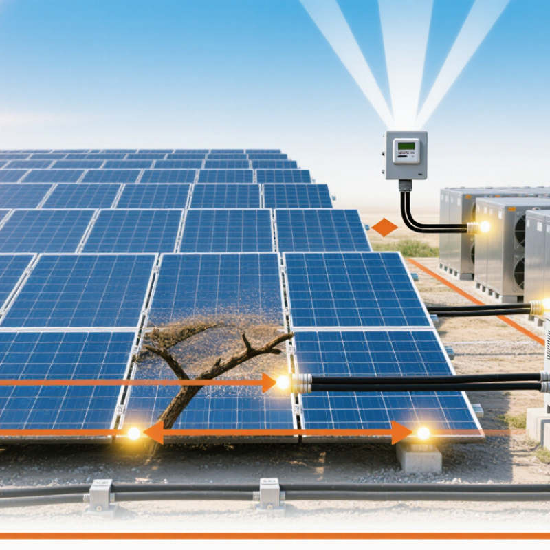
Tips: Measure losses instead of guessing. Compare panel temperature, irradiance, and output at the same time. Inspect connectors for discoloration, looseness, or heat marks. Keep cables short and correctly sized. Clean panels when dust visibly changes their appearance, but avoid harsh tools. Shade deserves attention. A narrow shadow from a railing can affect several connected cells.

Regular monitoring reveals patterns that a single inspection misses. A drop at noon may suggest heat or shading, while evening losses may indicate wiring or conversion limits. I have found that simple measurements often challenge initial assumptions. Perfect efficiency is unrealistic. Careful observation still makes the system better.

Identifying Loss Sources from Sunlight to Usable Electricity

How to Reduce Energy Loss in Solar Conversion Systems?

Identifying Loss Sources from Sunlight to Usable Electricity

Sunlight does not become electricity in one clean step. Losses begin when dust, glass, or poor alignment reflects incoming light. Shading from a narrow cable or vent can reduce an entire circuit’s output. A practical audit measures irradiance, module temperature, voltage, and current at the same moment. Compare these results with the system’s expected performance. Do not trust a single midday reading. Cloud edges and changing angles can hide the real pattern.

Inside the cell, spectral mismatch limits how much sunlight can be converted. Photons with too little energy may pass through unused. Excess energy becomes heat. High cell temperatures also reduce voltage and efficiency. Recombination inside the semiconductor removes charge carriers before collection. An infrared image can reveal hot cells, weak connections, or uneven loading. However, thermal images need careful interpretation. A hot spot may indicate a fault, but it may also reflect wind or surface dirt. A useful audit admits uncertainty.

After generation, cables, connectors, and protection devices consume additional power. Resistance in a long cable causes measurable voltage loss, especially during peak current. Measure voltage at both ends under load, not only during inspection. An inverter can lose energy through switching and temperature-related derating. Battery charging adds another conversion loss when storage is included. Small improvements often come from tighter connections, cleaner surfaces, better ventilation, and accurate control settings. Some losses remain unavoidable, which is why measured field data matters more than optimistic estimates.

Improving Solar Cell Efficiency and Electrical Output

Improving solar cell efficiency begins with controlling losses at every conversion stage. Sunlight reaches the cell, becomes electrical current, then travels through wiring and power electronics. Heat, resistance, shading, and poor alignment reduce usable output. A field assessment should measure voltage, current, module temperature, and inverter performance together. This creates evidence instead of relying on rated values. Real systems rarely match laboratory figures. That gap matters.

Tips: Keep cells cool with airflow and suitable mounting clearance. Clean dust from the surface, especially near unpaved roads or dry farmland. Use short, correctly sized cables to limit voltage drop. Check connectors for corrosion and loose contact. A calibrated multimeter and thermal camera can reveal hidden heating. Track output at similar sunlight levels, not only monthly totals. Small details add up. Yet aggressive cleaning can scratch protective layers, so maintenance methods need review.

Electrical output also improves when shading is mapped throughout the day. A thin shadow from a pole can affect several connected cells. Power electronics should operate near their efficient load range. Protection devices must match system ratings. I have found that simple inspections often uncover avoidable losses before expensive upgrades become necessary. Still, measurements can mislead when weather changes quickly. Compare repeated readings under stable conditions, and record assumptions. More equipment is not always better. Better data is.

How to Reduce Energy Loss in Solar Conversion Systems? - Improving Solar Cell Efficiency and Electrical Output

Energy-Loss Area Typical Loss or Impact Main Cause Recommended Improvement Expected Benefit
Optical Reflection Approximately 3–10% of incoming light may be reflected or lost before absorption. Front-surface reflection, unsuitable glass, and poor light coupling. Use anti-reflective coatings, textured surfaces, high-transmittance glass, and optimized module tilt. More photons enter the absorber, increasing short-circuit current and energy yield.
Spectral and Thermalization Loss A substantial portion of solar energy is unavailable because photons have insufficient or excess energy relative to the cell band gap. Low-energy photons are not absorbed, while excess photon energy becomes heat. Select an appropriate semiconductor band gap; consider multi-junction or tandem architectures for advanced systems. Improves the theoretical conversion potential and can raise efficiency beyond single-junction limits.
Recombination Loss Can reduce voltage and current, especially when defects or impurities are present. Electrons and holes recombine before reaching the electrical contacts. Improve material purity, passivate surfaces, reduce defect density, and optimize junction quality. Higher open-circuit voltage, longer carrier lifetime, and improved fill factor.
Resistive Losses Typically reduces fill factor and electrical output by roughly 1–5% in well-designed systems. Resistance in semiconductor layers, metal contacts, interconnects, and cables. Use low-resistance contacts, optimized conductor sizing, shorter cable runs, and reliable connectors. Higher fill factor, lower voltage drop, and improved delivered power.
Operating Temperature Crystalline silicon module power commonly decreases by about 0.3–0.5% per °C above the rated test temperature. Higher temperature lowers semiconductor voltage and increases thermal stress. Provide rear ventilation, avoid unnecessary shading obstructions, and use suitable thermal design. Lower operating temperature and better power output during hot conditions.
Partial Shading and Mismatch A small shaded area can cause a disproportionately large reduction in string output. Different irradiance levels, module tolerances, soiling, and uneven aging. Improve layout design, use module-level power electronics where appropriate, and group electrically similar modules. Reduces mismatch losses and improves energy harvest under non-uniform conditions.
Soiling and Surface Contamination Commonly causes about 2–5% annual energy loss, with higher values in dusty or dry locations. Dust, pollen, bird droppings, and other deposits block or scatter sunlight. Use an appropriate cleaning schedule, adequate tilt, drainage-friendly frames, and anti-soiling surface treatments. Restores light transmission and helps maintain stable energy production.
Inverter Conversion Loss Modern grid-connected inverters often achieve approximately 96–99% peak efficiency. Switching losses, magnetic losses, control circuits, and operation away from the optimal load range. Select an inverter with a suitable voltage and power range, maintain proper ventilation, and minimize oversizing or undersizing. Higher AC output and reduced conversion-related heat generation.
Maximum Power Point Tracking Poor tracking can cause avoidable energy loss during rapidly changing irradiance or temperature. Incorrect operating voltage, slow control response, or unsuitable string configuration. Use effective MPPT control, correctly size strings, and separate arrays with different orientations or shading patterns. Keeps the array closer to its maximum power point and improves yield throughout the day.
Cable and Connection Losses Usually designed below 1–3% of system output, depending on distance and conductor size. Long cable runs, undersized conductors, loose terminals, and corroded connections. Use correctly sized cables, secure weather-resistant connectors, and periodic electrical inspections. Reduces voltage drop, overheating risk, and long-term maintenance losses.
System Availability and Degradation Annual power degradation for mature crystalline silicon systems is commonly around 0.2–0.8% per year. Encapsulant aging, moisture ingress, thermal cycling, potential-induced degradation, and equipment downtime. Use robust materials, preventive maintenance, thermal and insulation monitoring, and rapid fault response. Preserves long-term output and increases the system’s lifetime energy yield.

Note: Values are representative engineering ranges. Actual losses depend on cell technology, climate, installation design, operating conditions, and maintenance practices.

Reducing Losses in Power Electronics and Energy Storage

Reducing energy loss in solar conversion systems starts with the power path, not the panel label. During field testing, I have seen warm connectors consume more energy than expected. A clamp meter and thermal camera can expose these hidden losses. Small faults matter. Use short, correctly sized cables, clean terminals, and tight connections. Every extra resistance point converts useful electricity into heat.

Inverters and DC-DC converters need careful operating ranges. Choose switching frequencies and semiconductor ratings that match real current peaks, not ideal specifications. Oversized components may reduce electrical stress, but they can increase standby consumption and cost. Cooling also deserves measurement. A blocked vent raises temperature, increasing resistance and shortening component life. Control software should track voltage, current, temperature, and conversion efficiency under changing sunlight. This data reveals losses during startup, partial load, or high output.

Energy storage adds round-trip losses during every charge and discharge cycle. Keep batteries within their recommended temperature and state-of-charge range. Avoid charging immediately after a cold night without checking cell conditions. That habit is easy to overlook. Use balanced cells, low-resistance busbars, and protection settings based on measured behavior. A storage system can appear efficient on paper yet lose energy through idle loads, fans, and conversion stages. I would not trust one efficiency reading. Compare daily data across seasons, then revise assumptions when results disagree.

Monitoring System Performance and Optimizing Energy Conversion

Reducing energy loss in solar conversion systems starts with reliable performance monitoring. A modern monitoring platform should track irradiance, module temperature, inverter output, voltage, current, and grid conditions at short intervals. These measurements reveal whether losses come from shading, soiling, overheating, wiring resistance, or inverter clipping.

According to the International Energy Agency Photovoltaic Power Systems Programme’s 2024 market snapshot, global solar capacity exceeded 1.6 terawatts in 2023. At this scale, even a one percent monitoring error can represent substantial lost generation.

Useful monitoring compares actual output with a weather-adjusted model, not with yesterday’s production alone. Operators can calculate performance ratio, inspect daily loss waterfalls, and set alarms for abnormal string current or repeated inverter shutdowns. Thermal inspections can identify hot connectors, while periodic IV-curve testing can expose mismatch and hidden degradation.

NREL’s analytical review of photovoltaic degradation rates found a median annual degradation rate near 0.5%. That figure should influence long-term energy forecasts and maintenance budgets.

Small improvements matter. Cleaning schedules should follow measured soiling rates, rather than fixed calendar dates. Ventilation around conversion equipment must remain unobstructed. Control settings also need review during high-irradiance periods, when clipping may increase. A dashboard can still lie when sensors drift or data gaps go unnoticed. Therefore, calibration checks and manual field inspections remain necessary. Perfect optimization is unrealistic. Better decisions come from questioning clean-looking data.

FAQS

What causes energy loss before sunlight becomes electricity?

Dust, glass reflection, poor orientation, and shading reduce the light reaching solar cells. Some sunlight becomes heat instead.

How does heat reduce solar system output?

Hot panels usually produce less power, even under strong sunlight. Resistance in cells and cables also creates unwanted heat.

Can a small shadow affect several solar cells?

Yes. A narrow railing shadow can reduce output across connected cells. Small shade deserves attention.

How can operators find hidden electrical losses?

Compare irradiance, panel temperature, voltage, current, and output together. Thermal images can reveal warm connectors and loose terminals.

What cable and connector practices reduce wasted energy?

Use short, correctly sized cables. Keep terminals clean and tight. Replace discolored connectors or heat-damaged parts.

How can inverter and converter losses be reduced?

Match operating ranges to real current peaks. Keep cooling vents clear. Review performance during startup, partial load, and high output.

Why does energy storage lose power during charging and discharging?

Batteries lose energy during every round trip. Idle loads, fans, resistance, and conversion stages add further losses.

How should battery systems be monitored?

Keep cells within recommended temperature and charge ranges. Check cold conditions before charging. Use balanced cells and measured protection settings.

How can monitoring improve solar conversion efficiency?

Track sunlight, module temperature, inverter output, voltage, current, and grid conditions frequently. Compare results with weather-adjusted expectations.

Can monitoring data be trusted without field checks?

Not completely. Sensors can drift, and data gaps may look harmless. Manual inspections still matter. Perfect optimization is unrealistic.

Conclusion

Reducing energy loss in solar conversion systems begins with understanding how sunlight is transformed into usable electricity. The question “what causes energy loss in solar conversion systems” can be answered by examining several stages, including reflection, shading, heat buildup, cell resistance, wiring losses, and imperfect conversion of light into electrical current. Identifying these sources helps system designers target the areas with the greatest impact.

Improving solar cell efficiency requires effective light absorption, temperature control, low-resistance electrical connections, and proper system positioning. Additional losses can occur in inverters, converters, batteries, and other storage components, so selecting efficient equipment and managing charging and discharging carefully is essential. Regular monitoring of voltage, current, temperature, and energy output can reveal performance declines early. By analyzing operating data and optimizing each conversion stage, solar systems can deliver more reliable electricity, reduce waste, and achieve better overall energy performance.

Henry

Henry

Henry is a dedicated marketing professional with a profound expertise in the company's offerings. With years of experience in the industry, he possesses an impressive understanding of the market dynamics and consumer behaviors that drive success. Henry is committed to sharing his insights through......